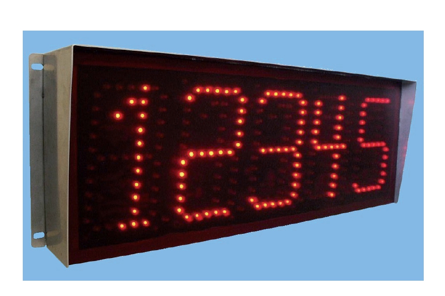
Receiving data from RS232, RS485, RF 868 MHz.
Alphanumeric display to 5 characters / digits, height 160 mm, brightness automatically adjusted and suitable for external installation
Container in stainless steel and watertight logons.
Connects to all instruments of our production.
Configuration and customization protocol with PC software.
Download installation and usage manual ![]()
![]() Click to enlarge image
Click to enlarge image

| Power supply | 100 - 240 V ac – 50 / 60 Hz | |
| Max power consumption | 25 VA | |
| Operating temperature | -10 / +40°C (14 °F / 104°F) Humidity maximum 85% non-condensing | |
| Storage temperature | -20 / +50°C (-4 / +122°F) | |
| Display | Alphanumeric 5-digit dot matrix high-efficiency red LEDs with a wide viewing angle | |
| Reading distance | Up to 130 feet | |
| Display brightness | Anti-reflection filter and automatic brightness adjustment in ambient light function. Suitable for direct light installation | |
| Overall dimensions | 656 x 230 x 110 mm / 25.8 x 9.1 x 4.3 in (l x h x p) | |
| Mounting | Wall-mounted with 4 external side holes Ø 6,5 mm with center distance 635 x 195 mm (l x h) | |
| Case material | Stainless steel protected against dust | |
| Protection level | IP 65 | |
| Connections | Waterproof circular connectors with conductor wiring with screw terminal | |
| Communication ports | Rs232c / Rs485 standard | |
| Max. cable length | 15m (Rs232c) and 1000m (Rs485) | |
| Serial protocols | ASCII + programmable custom protocols | |
| Baud rate | From 1200 to 115200 selectable | |
| Options | Ethernet protocol and Profibus protocol | |
| Optional interface RF 433 MHz | Coupled operation with transmitter module to be combined with the transmitter weighing instrument | |
| Num. RF Channels | Up to 7 channels selectable on the 868 MHz band for installation of multiple systems in the same area | |
| Average radius of coverage | 100 meters in free air | |
| Conforms to standards | EN61000-6-2, EN61000-6-3, EN61010-1 | |
| Type | J1 5 poles serial female |
| Length | ND |
| 1 | GND + Shield |
| 2 | RS232 Rx |
| 3 | RS485 - |
| 4 | RS485 + |
| 5 | RS232 Tx |
General precautions to be followed in the installation and assembly of load cells: